A Great Inverter Upgrade for More Power
Designing the Inverter Upgrade
As the solar power system at Roy Creek Ranch expanded, a new challenge emerged: electric vehicle charging. While the existing system worked well for general use, it struggled to deliver the sustained power required for Level 2 EV charging.
This post documents a major turning point in the project—the transition from a single inverter system to a scalable, high-capacity architecture capable of supporting both daily energy needs and EV charging. Along the way, it also exposed the complexities of integrating battery management systems with modern inverter technology, leading to a deeper level of system design and control.
The inverter I installed in 2020 was limited to 6000 watts output, not enough to reach the minimum specification for Level II charging, 7500 watts. Also, it had some problems starting with the charging loads. I often had to start the charge at a lower rate and adjust the rate upwards to something like 5000 watts. Workable, but something better would be nice.
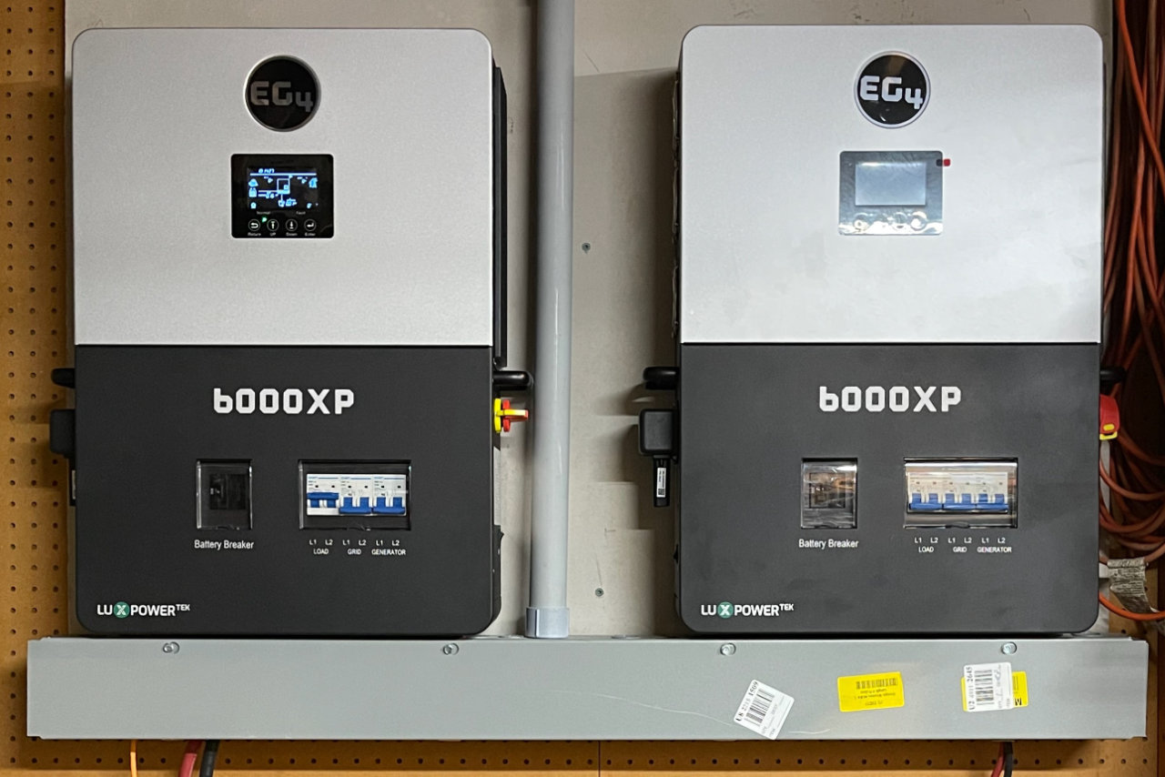
The EG4 6000XP
After looking at the many inverters on the market, a friend of mine recommended the EG4 product line. In particular, the 6000XP stood out for my needs. Like the current inverter, it combined an inverter, solar charge controller, and a 240-volt battery charger that could use an ICE-powered alternator and charge the system batteries when the sun wasn’t shining. It added several other features though:
- Two MPPT inputs, up to 480Vdc max
- MPPT operating voltage range: 120-385V
- Max. usable input current per MPPT: 17A
- Max. short circuit current per MPPT: 25A
- Max. utilized solar power: 8000W
- Max. charge/discharge current: 125A/140A
Earlier, I had already upgraded the legacy charge controller with a Victron MPPT 250|100, but the 6000XP could handle a greater range of inputs, and there were two of them!
Wi-Fi Enabled
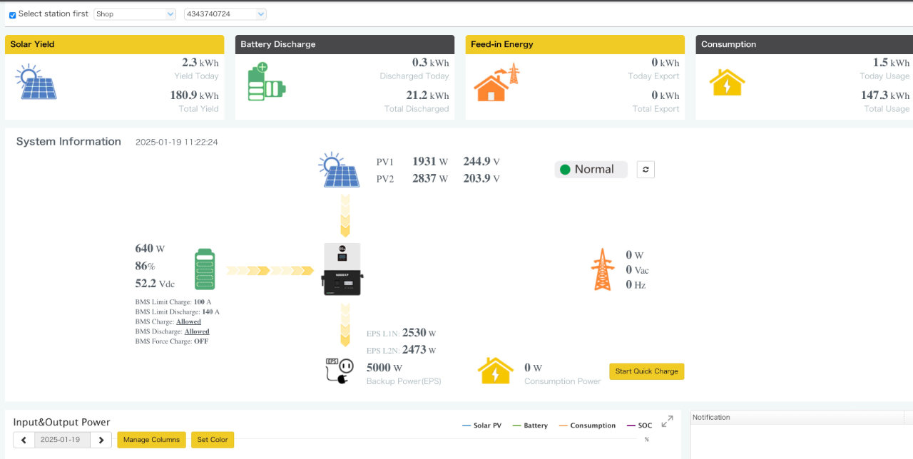
There was a bonus feature though: remote monitoring through the Web. The 6000XP could connect to my Wi-FI, and had an iOS app so I could check on operation of the device anywhere around my home or even off-site. Not only could the app show current conditions, it also kept statistics that could be displayed in graphical charts or even exported to other software.
Expansion
But 6000 watts was the same as the existing inverter. No problem, more 6000XPs could be added. Up to 16 of them. Each added inverter synchronizes with the primary inverter through an Ethernet cable, and you simply combine their outputs in a standard Load Center. All of this for around $1550. I ended up buying two for a total output of 12,000 watts. Enough to charge the car quickly and also provide substantial emergency power to the house in the event of a power failure.
Uncle Sam would help too
With a 30% rebate courtesy of the “Inflation Reduction Act”, it was a no-brainer. Several other parts were needed as well:
- Cable trough
- Conduit
- 16-circuit load center
- 20-amp circuit breakers
- BMS upgrade
- High-current primary cables
- high-current Anderson power connectors
- 3/4-inch plywood
- Cement board
- various other hardware items: screws, wire, connectors, etc.
The Build
I cleared a section of wall in the shop big enough to hang the two inverters. In some ways, that was the hardest part because my shop is stuffed to the gills. It was a good excuse to “de-accession” a few things — something I had been meaning to do for some time.
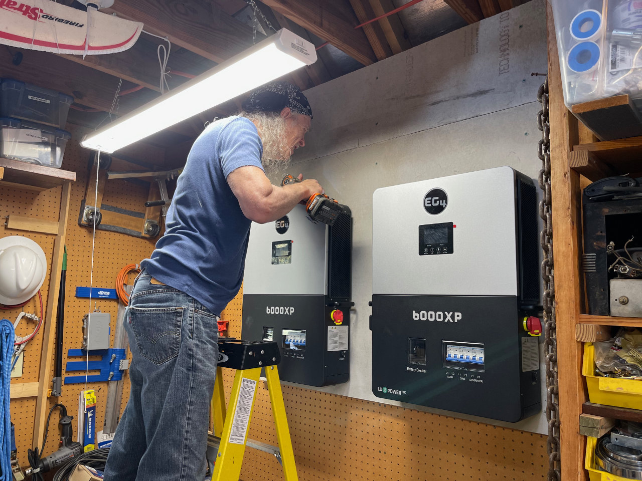
The inverters must be mounted on a non-flammable surface. Since the shop is a wood-frame building, this meant a layer of 3/4-inch plywood topped with a layer of cement board. My friend Joe came over and helped me lift and secure them to the wall.
The inverters each weigh about 65 lbs, and must have a specified amount of space between them and other flammable materials. This is for both electrical safety and to allow for adequate cooling. The details are all in the supplied installation manual. EG4 also provides a cardboard mounting template to position the devices and mounting hardware. We had them mounted in about 20 minutes.
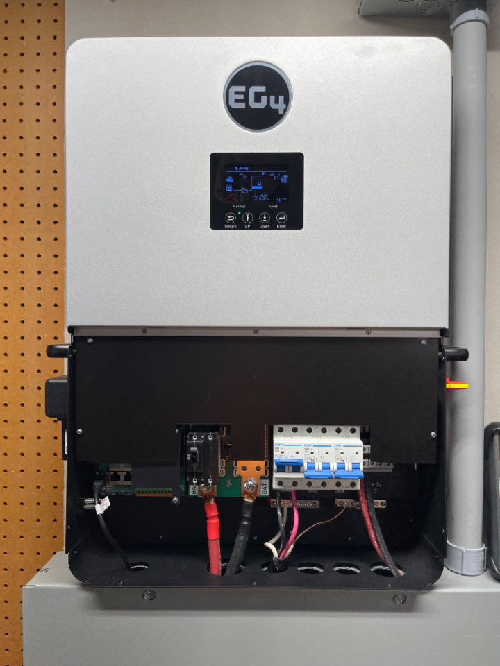
Cabling
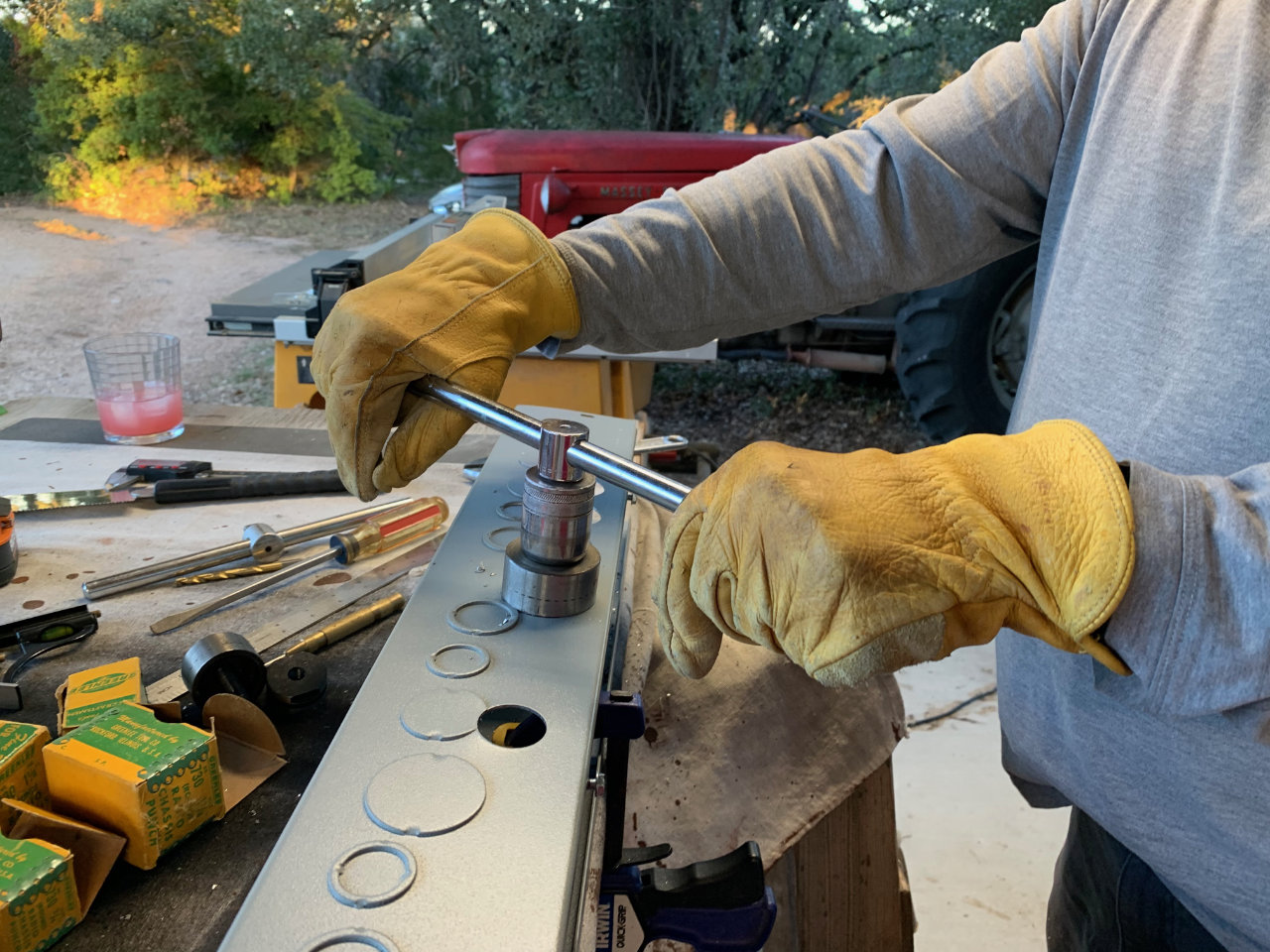
There are knockouts on the bottom of the inverters for cabling. EG4 provides a custom cable trough that supports two inverters for about $100, but standard 6-by-6-inch square cable trough will work just fine at about half the cost. The custom EG-4 trough has holes that match the inverters already cut, but it didn’t take long to mark and cut the holes I needed with metal hole punches.
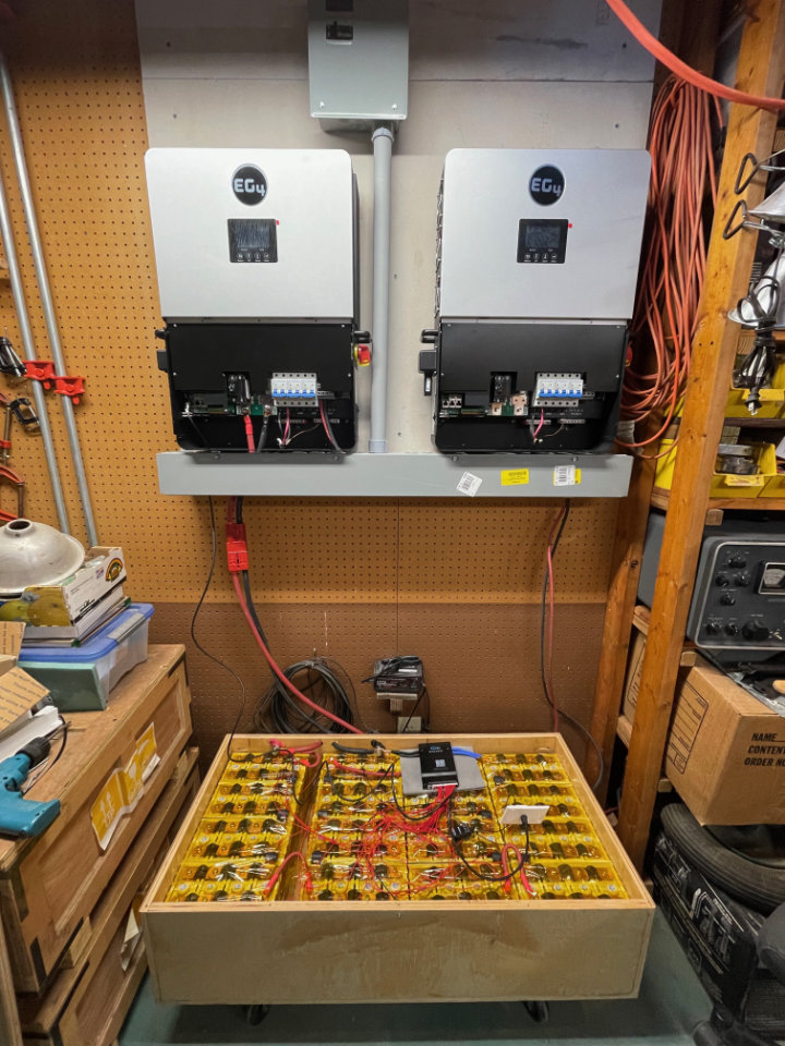
In my installation, all the photovoltaic (PV) lines enter from the right side of the trough and route through the building to the same junction box I used in the first installation. Battery connections are made with 180-amp Anderson Power Poles through the bottom of the trough to the battery boxes below.
A metal conduit exits the top of the trough between the two inverters and terminates in the bottom of a load center, located above and between the two inverters. The Load Center has two breakers, one for each inverter and combines their output. Power out from the inverter system travels along an NM-B 6/3 cable to connect with the main shop load center.
No additional circuit breakers are needed because the 6000XP has breakers for Battery, Load and PV included.That’s a substantial savings too!
Upgrades to the Battery Box
I planned to re-use the existing 240 Amp Hour Lithium Iron Phosphate (LiFEPo) battery I had constructed for the earlier inverter. Several upgrades were needed to make that work however. In the original system, two heavy gauge primary wires were the only connection between the battery and the inverter. Although the battery had a Battery Management System (BMS), it only provided data to an iPhone app. Useful for configuring and monitoring, but no communication between the inverter and battery.
The 6000XP Inverter integrates more fully with the battery. EG4 has a companion line of battery products that work with their inverters. Besides the heavy primary cables, a CAT-6 network cable connects between them. Data from the BMS is shared with the inverter, allowing it to manage charging the battery and powering the inverter in an intelligent fashion. In fact, the inverter won’t even start if this battery communication system isn’t connected.
The 6000XP supports two battery communication protocols: RS-485 and CAN. It was disappointing to learn that my existing BMS, the Overkill JBD (48-volt, 16S) did not support serial connections. Nuts! I had purchased two of them to provision two battery boxes, and only used one so far. One was still brand new in the box.
A New Battery Management System (BMS)
It wasn’t too hard to find a replacement though. The JK-BMS Model B1A20S15P would suit my needs. They were half the cost of the Overkill models I had purchased the previous year, and would handle up to 200 amps of battery current. The docs said they could also support RS-485 communication with the addition of an external adapter. It looked like I was all set.
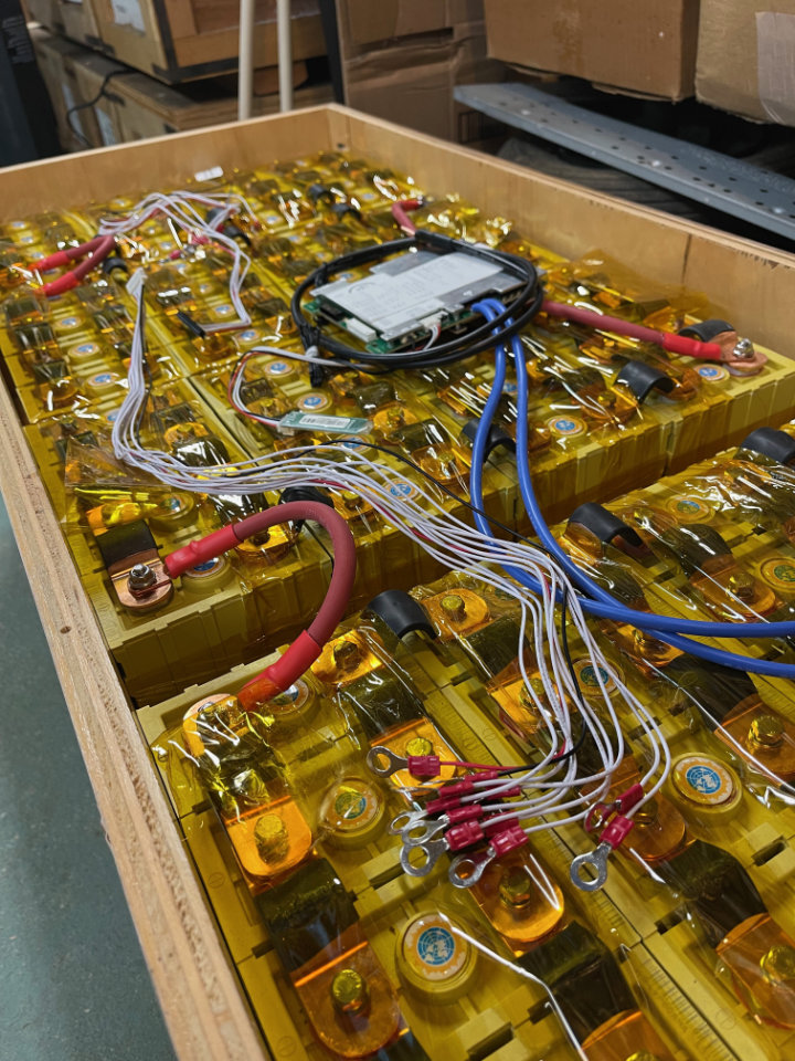
Wiring the BMS
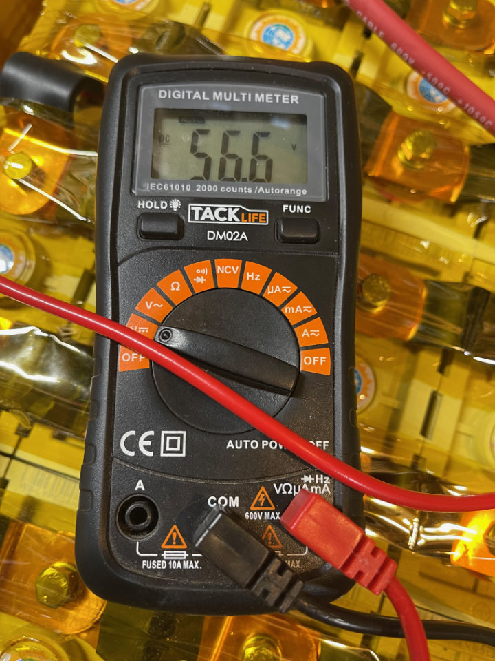
Cabling for the BMS is very similar to the Overkill model, although not exactly the same. I had to remove the Overkill wiring and replace it with the JK-BMS version. Working carefully, I checked each pin of the multi pin miniature plug for proper wiring. As one measures the voltage on each pin in order, the measured voltage should increase by 3.3 volts or so. If it doesn’t, and jumps around with various voltages at sequential test points, re-check the wiring. If the voltages are out of order when plugged in, it will toast the BMS! Be very sure of this!
Configuring the BMS
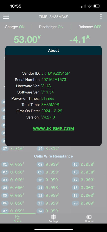
Like the Overkill model, JK-BMS provides an iOS app for configuration. It communicates with the BMS via Bluetooth, and connects easily. I won’t go through the settings here, because I am far from expert. If you don’t already have an idea of how this should go, then the Off-Grid Garage gives a pretty good explanation: Check his “My Settings” page for info. I’ll mention his YouTube channel later.
It’s working . . . Sorta
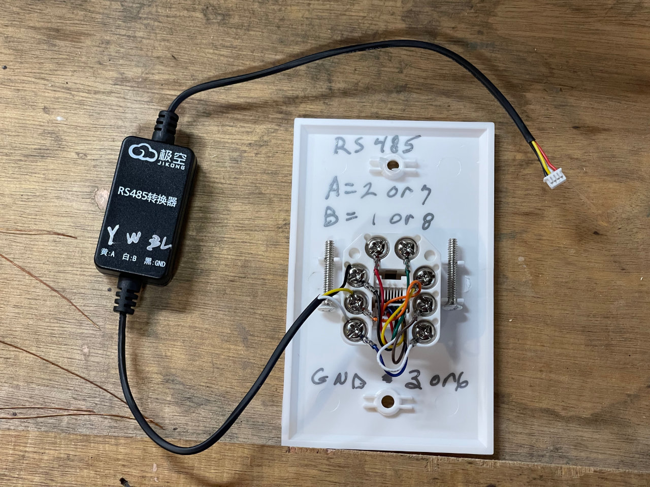
The external RS-485 adapter comes with a miniature plug that fits the JK-BMS connected through a small “dongle” to stripped wire ends. Of course, the instructions were in Chinese, but a little work with Google Translate provided signal connections and wire colors. Then, using the wiring information provided in the 6000XP manual, I connected an Ethernet jack to the wired ends. Thinking I was very clever, I then began the commissioning process: power up, a few settings and . . . No Joy. The inverter couldn’t find the data connection. More careful study of the manual revealed I could use the “lead-acid” setting for battery type to power the inverter. Not ideal, but at least I could get power out of the system until I fixed the data problem.
A Walk through the BMS wilderness
Much more research on the ‘web and YouTube ensued. I’ll spare you the gory details, but the “Off-Grid Garage,” from a very helpful Solar Enthusiast in Australia, seemed to have the answer. It seems he had tried about every combination of batteries, inverters and Battery Management Systems and recommended adding an intervening device between the JK-BMS and the 6000XP. He is entertaining the very knowledgeable, so here’s the video if you’d like to hear it from the man himself.
Solution: iBMS
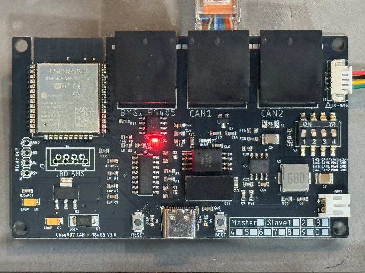
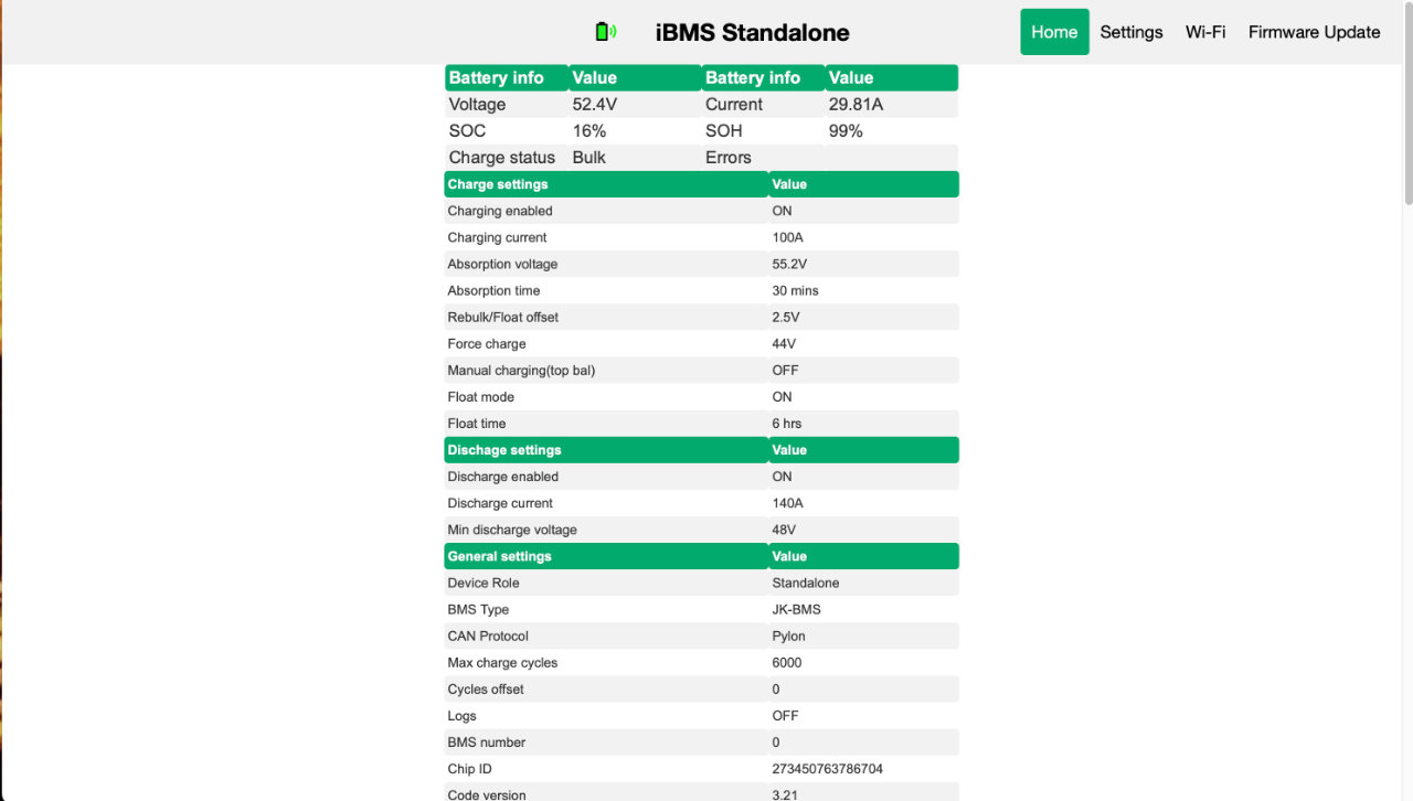
The iBMS arrived from Australia in about a week, and I had it working pretty quickly. A 4-pin miniature cable connects the iBMS to the JK-BMS. A CAN Bus (RJ-45) then connects the iBMS to the inverter. iBMS sets up its own little web server, available through your local network. All of the settings in the JK-BMS are shown but the real magic is the ability to change certain settings without modifying the actual JK-BMS settings. This means a second layer of protection for the batteries, while allowing a level of customization that the JK-BMS doesn’t support.
Home Assistant too!
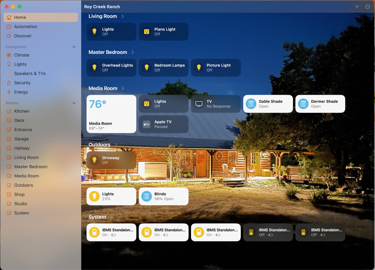
On top of that, iBMS provides an integration for Home Assistant (home automation) so that your battery condition can be viewed in Home Assistant. HomeKit (Apple Home) can gain access to these data and settings through the Home Assistant Bridge. Other than confirm it works, I haven’t delved much into this yet. I plan a series of posts on my home automation efforts in the future though. So stay tuned.
Success!
At this point, I have a fully-integrated PV -> Charge Controller -> LiFEPo Battery -> Inverter System. I have measured peak solar capture of about 5500 watts and have charged the Ioniq5 at up to that amount. The second inverter it mounted and wired into the power combiner box, but the second battery is not complete. A second 6 KW PV array is planned for late 2025 as well.
Solar Resilience Project Series
Follow the evolution of the Roy Creek Ranch solar system:
Phase 1 — Foundational Systems
- Solar Power for the Amateur Radio Station (2015)
- Solar Powered Rainwater Project (2017)
- 2 kW Shop Solar System (2019)
- Build a Handy 12-Volt Solar Generator with LiFePo4 Batteries (2023)
Phase 2 — Expansion & System Upgrades
- Solar Power System Upgrade (2022)
- The Really Big Lithium Battery (2023)
- Solar EV Charging — Ioniq 5 (2024)
- Inverter Upgrade for EV Charging (2025)
- Solar Garage EV Charging (2026)