Finishing the Really Big Lithium Ion 48-volt Battery
Preliminary steps
With the completion of 95 copper bus bars, I was nearly ready to assemble the Really Big Lithium Ion Battery. There is a little process involved though. The Lithium Iron Phosphate (LiFePo) cells I was using had been in storage for a while and though new, would need a some maintenance. There would be 64 of them, arranged in 16 sets of four cells.
Battery Safety
When creating a high-energy battery, we have to talk about safety. Each of the 64 cells can store almost 200 watt-hours of energy. With 64 of them in the box, that’s over 12,000 watt-hours! Releasing that energy, to paraphrase Space-X lingo, in an unscheduled rapid discharge, would make for a very bad day.
The battery terminals are located on the top of each cell. Also, the cells are connected to each other with short copper bus bars. With a peak voltage of up to 57 volts inside the box, a metal wrench or screwdriver dropped in just the right place could create quite a display of sparks. It might even weld that tool to the battery terminals so it couldn’t be removed. Discharging this rapidly will cause the cells to heat up dramatically and could cause a fire that cannot be extinguished with water. Taking precautions and working methodically are essential.

I take two specific precautions: wrapping metal tools with electrical tape and shielding the battery terminals with Kapton tape. By wrapping metal tools completely, except the part that actually drives the screw or bolt, we can limit the chance of the tool accidentally shorting two terminals. I also use Kapton tape, a versatile adhesive tape known for its exceptional heat resistance, electrical insulation, and chemical resistance, to insulate all the top-facing cell terminals that I’m not actually working on.
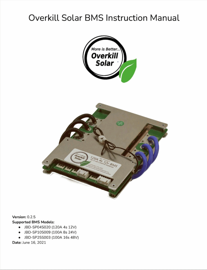
The good folks at Overkill Solar, the suppliers of the Battery Management System (BMS), have put a list of hazards together in section 2.1 of the JBD BMS manual that is essential reading. It contains this advice:
If you are completely confident in your abilities, turn back now. Fear keeps you alive.
What follows is a summary of the steps I took to build my own battery. The entire process is described in detail in the JBD BMS manual. It’s a very detailed process and can probably serve as a guide for most other models. There are many BMS models out there though, so it would be wise to follow the documentation for the BMS you use.
Finding 64 matched batteries
As mentioned in the introductory post, I planned to use cells purchased from a friend’s surplus business. To recap, the cells were new, but had been in storage for some time. If they had been lead-acid or even gelled lead-acid cells (AGM), I wouldn’t have considered using them because those chemistries deteriorate over time — even without use. The LiFePo4 chemistry is different however. It has a very long shelf life, and the cells still measured around 3.3 volts even though they hadn’t been charged since manufacture. About the same as when they left the factory. That said, there were still minute differences between individual cells. I had several boxes of them, and carefully measured each cell to find 64 that matched voltage as closely as possible. That would shorten the balancing process.
Top-balancing
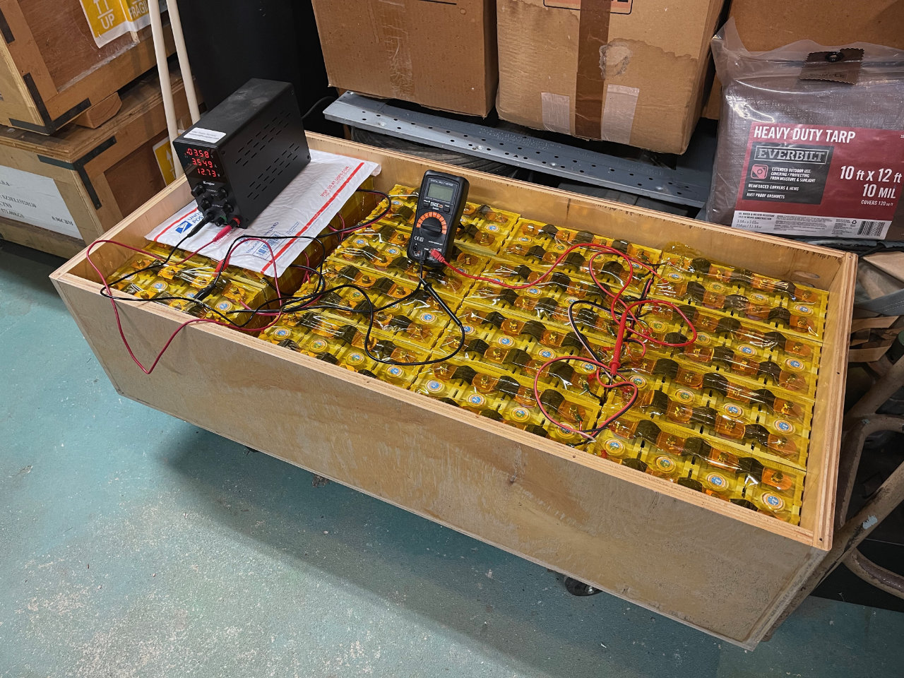
Top balancing lithium cells involves equalizing the voltage of all cells at full charge, ensuring consistent performance, longevity, and safety across the battery pack. To do this, the cells are connected in parallel to make a giant 3.3-volt battery. We then connect a small power supply with both voltage and current regulation. It is set to the maximum charge voltage of the cells, 3.6 volts, with a current limit of 10 amps. Depending on the overall capacity of the battery, this process can take a while — perhaps several days — since the charge current drops dramatically as the cells near the final voltage. This is not a very exciting process, but essential if the battery is to perform efficiently. Don’t leave the process unattended. Keep an eye on it — just in case.
Building 12-volt “sub-batteries”
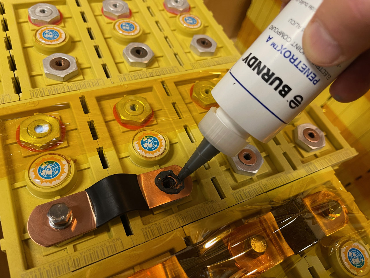
Because of my relative inexperience, I decided to build the battery in four sections of 12-volts each. I had a spare 12-volt BMS, and with it I could check the performance of each section independently before assembling them into their final 48-volt configuration. But first, cleaning. The aluminum terminals had a little oxidation. Using a small electric drill and a rubber pad coated with fine abrasive, I gave each terminal a polish. Remember, each cell could be charged or dis-charged at rates of up to 40 amps. Even tiny amounts of oxidation could cause significant resistance and therefore voltage drop in the battery. To further improve contact between the aluminum terminals and the copper, I also added a small dab of Burndy Penetrox Electrical Joint Compound. This will also reduce further oxidation during the battery’s service life.
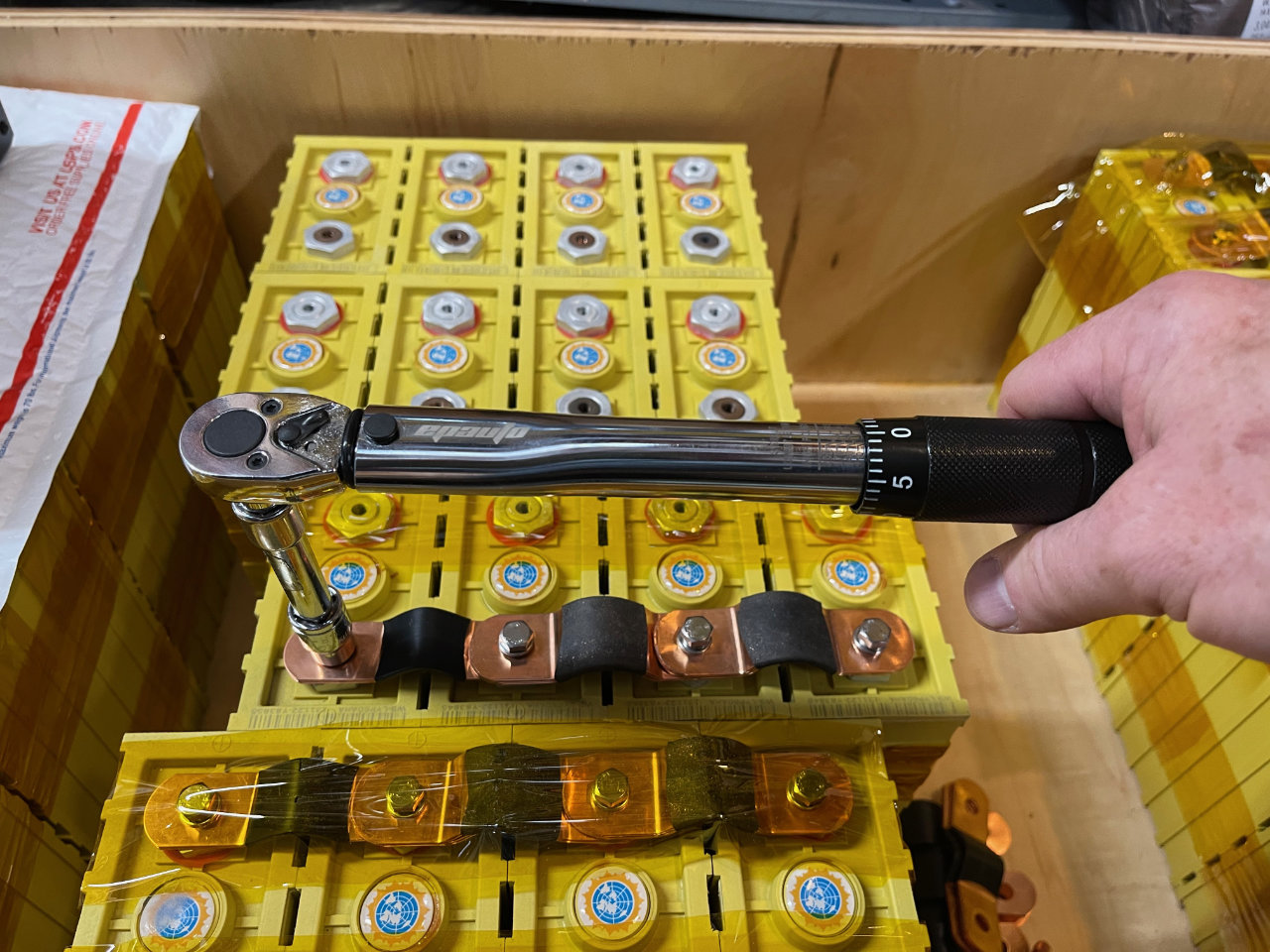
Tightening the bolts that attach the copper straps to the cells to the proper torque is important. I consulted the spec sheet for the “Winton” cells to find that specification and used a torque wrench.
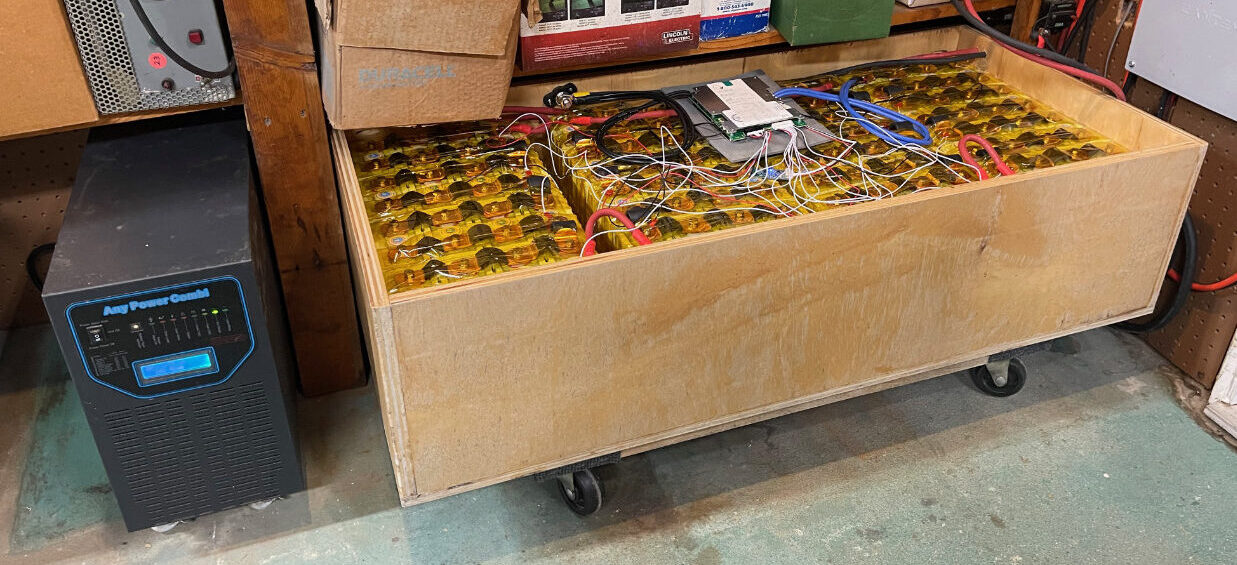
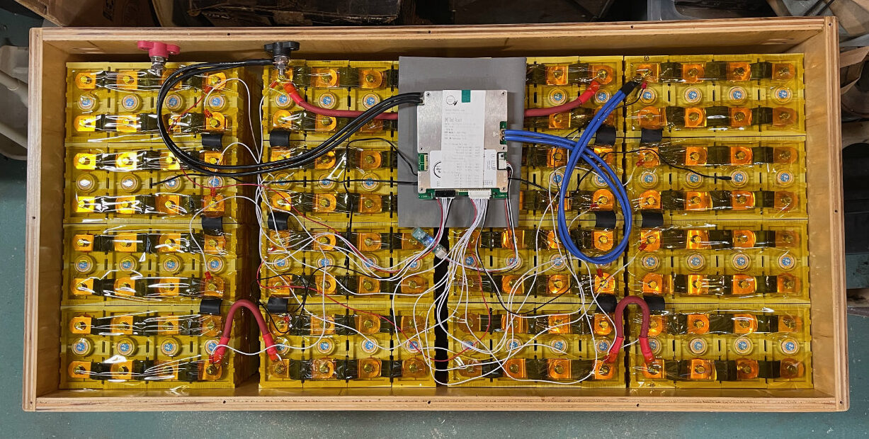
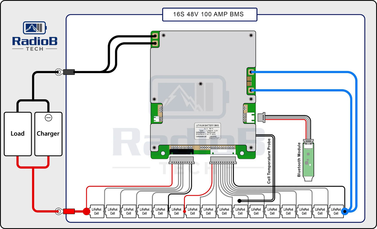
I also used Kapton tape to group cells into 4-cell packs. Then, four packs are taped together into 12-volt assemblies. Four of these assemblies will just about fill the battery box. Once assembled, I connected the BMS as described in OverKill Solar’s instructions.
Load testing with an inverter
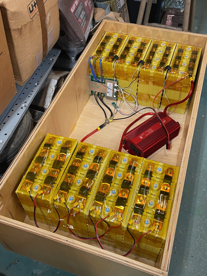
Load testing is pretty simple. I use a Bestek 1000-watt inverter to power a pair of 300-watt construction lights. To do it right, one should discharge the 12-volt battery pack to no less than 20% of the battery’s capacity. I like to use the Victron Energy Blue Smart IP67 charger to re-charge the battery because it provides an extra layer of battery safety.
Each of the 12-volt assemblies is tested in the same fashion, moving the 12-volt BMS from one to another. After successful testing, the 12-volt sub-batteries are all connected in series to make the 48-volt battery. Of course the 12-volt BMS is replaced with a 48-volt one. Be sure to add a suitable circuit breaker for overload protection and to provide a convenient way to disconnect the battery from its load. 1/0 AWG welding cables and a 175-amp Anderson Powerpole are used to connect the inverter.
In Service
The battery has been in service for some time now, and I’ve had no problems. By the time you read this, the specific BMS I used will have changed. It’s a very fast moving technology. The good news is that whatever you buy for your project will be better and cheaper than the ones I found. Mainly, I wanted to show one possible strategy and report my experience. Many other possibilities exist.