Solar Powered Rainwater Project – Final Assembly
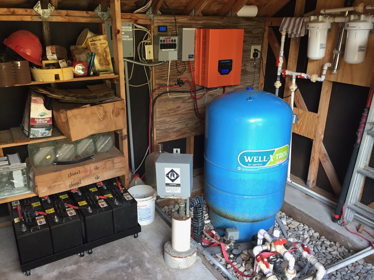
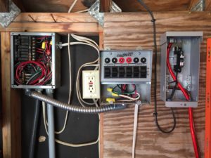
With all the parts in stock, it was time to assemble the whole Solar Powered Rainwater Project. I cleaned out a space in the garden shed, and added plywood to the wall for attaching the various components. We would be mounting the inverter/charge controller, solar panel combiner/breakers, A/C transfer switch and related wiring.
Mount up!
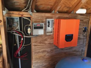
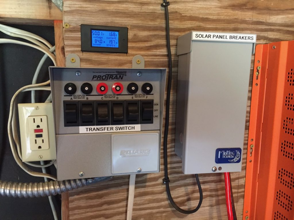
The inverter/charge controller was first. At about 100 pounds, it was too much to handle alone, so my friend Norman helped. The good news was that the inverter mounting holes were 15 1/2-inches apart — perfect for mounting to a wall with 16-inch-on-center studs. That done, we mounted the solar combiner box and transfer switch.
Connecting the Solar Panels
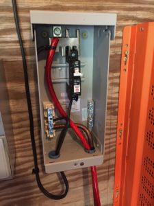
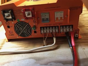
Wiring the solar panels was next. The two, 24-volt panels are connected in series to produce 48 volts, so only one 2-conductor wire was needed. I used 12-gauge landscape wire because it is relatively inexpensive and is intended for outdoor service. Assembling the DC breaker into the solar combiner box was simple, and the box has space for two more breakers to connect additional 48-volt panel strings. Another pair of heavy wires connects the combiner output to the DC input on the inverter/charge controller.
Wiring the A/C Mains
The next connections to the inverter were for 240 VAC power. Commercial power is connected to the input, and the output connects to the transfer switch in my system. This way, we can select either solar generator or commercial power for each load; water well, greenhouse (with the rainwater system), lighting and outlets. It’s an added complication, but otherwise I would have to power everything with either solar or commercial power at the same time.
The A/C Transfer Switch
Now, the transfer switch. These are commonly used with generators so that each load can be selectively powered by either the generator or commercial power. It has the added advantage of preventing generated power from connecting to the commercial power grid. This is very important because linemen working on the commercial grid during a power outage are not expecting supposedly “dead” power lines to have power, and might be injured. This keeps everyone safe.
Configuring the Inverter and Connecting the Batteries
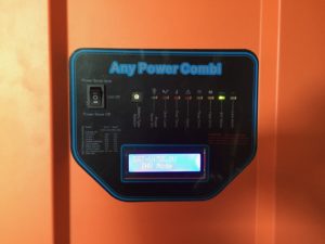
After mounting the 200-amp DC breaker and connecting the batteries, we were ready for testing. I configured the inverter/charge controller according to the manual and DIP switches were set for Deep-cycle battery, utility power mode, 60 Hz line frequency and battery priority. Even though I had checked each connection made over the last few days, there was still a little thrill of anxiety — did I get it all right? Also, would the inverter be stout enough to power the well pump? If it worked, I could be sure that the rainwater system would work since it uses only half as much power.
But will it work?
Time to power the inverter. The lights on the front flashed with their self-test and the “inverter” LED stayed lit. Everything was powered. As I threw one of the transfer switches for the garden shed lights to the “GEN” position, they didn’t even blink. They were running on the inverter. Now, the outlets that power the ultraviolet filter. Again, not even a blink — still running. Moment of truth time. A sprinkler was running in the garden and soon it would start the well pump. I flipped the switches for the well pump to “GEN” and waited. The pressure switch clicked on, and the well pump started humming. The inverter had started a 1 1/2 horsepower well pump. Success. We would be celebrating tonight!
Measuring the results
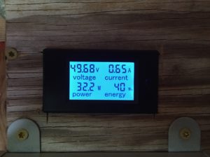
Finally, I installed the last element of the system — a digital meter that measures voltage, current and wattage drawn from the battery bank. With it, I can see the battery voltage change as sunlight and power loads change — confirming that the solar panels and MPPT charge controller are working as expected. What I know already is that we’ll need two more panels. My calculations predicted this, but I didn’t realize that the inverter draws a constant 70 watts when powered. That, combined with the power used by the ultraviolet filter (about 30 watts) mean that most of the power generated by two panels in 24 hours is used each day. 100 watts times 24 hours is 2400 watt/hours used. 500 watts of solar panel times an insolation of 5 is about 2500 watt/hours of power generated. Most of the power generated is being used by small, but constant power drains that cannot be avoided. Still, we have a complete, working system to learn on. Very exciting! Now — about those panels . . .
Pingback:Solar Powered Rainwater Project – Batteries | Roy Creek Ranch
Awesome; more than interesting! There is so much here to see and learn. I only spent an hour; but, I was amazed and entertained the whole time. I believe I’ve only scratched the surface. You did a great job making this record and archive!
Thanks! More to come!
Jim – always doing something interesting! Well, here’s an item of interest; Frank Simon is retiring from UT. There’s a small gathering on Monday, August 28, in front of Bates Recital Hall. Please come. I’d also like to contact Bill Howell.
Congratulations, Frank! Sound like fun. What time?
Pingback:Solar Power Rainwater System – More Panels! | Roy Creek Ranch