Build a Handy 12-Volt Solar Generator with LiFePo4 Batteries
Building a Solar Generator
Batteries
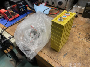
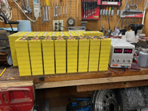
Previously, I wrote about Upgrading a Solar Power System and mentioned a cache of new Lithium Iron Phosphate (LiFePo4) cells. The “ThunderSky Winston” cells had come from a Segway repair operation and were new. A little looking around the ‘net revealed they were still available from GWL Group. With a capacity of 60 Amp Hours (AH) and nominal voltage of 3.3 volts, they looked useful for building high density batteries.
Prior to getting those cells, I had no previous experience with the LiFePo4 battery chemistry. So in order to learn about them in a “low-stakes” application, I decided to make a “Solar Generator.” These have become popular lately. By using four cells connected in series, I would end up with a 12-volt, 60 amp-hour battery — suitable for many uses around the ranch.
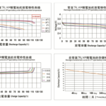
The data sheet reveals several other important considerations. The cells have a 60 amp-hour capacity (or C). Their optimal discharge rate is 0.5 C, but can be discharged at up to 3 C for a maximum of 15 minutes. Discharging below 2.5 volts or charging above 4 volts will damage the cells. They should not be operated above 80C or charged below freezing. That’s a lot to keep track of, and why the project would also incorporate a “Battery Management System” or BMS, to manage all of those parameters.
Battery Management Systems
Battery Management Systems are available in a variety of configurations and are programmed to safeguard the individual cells by charging them with the manufacturer’s recommended profile. They also protect LiFePo4 batteries from under or over charge, excessive discharge current, over-temperature, and prevent charging below freezing temperatures which will destroy LiFePo4 batteries.
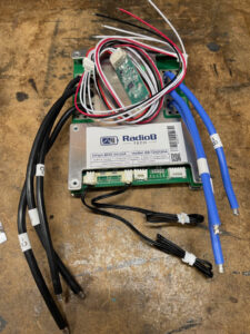
The RadioB Tech Smart BMS 4S 12V 120A Lifepo4 Lithium Battery Management System is a little larger than needed for my application, but available at a reasonable price. I also wanted to gain experience with this model since I intend to make larger batteries in the future.
BMS devices are normally rated by the number of cells in series, nominal output voltage and maximum output current. In this case “4S 12V 120A” becomes 4 cells in series with a nominal output voltage of 12 and maximum current delivery of 120 amperes. The BMS disconnects from loads over that. Keep in mind that the BMS can be programmed to disconnect with smaller loads, customized to fit the job.
Other bits and pieces for the Solar Generator
With LiFePo4 cells and BMS in hand, a few other components were needed to make a functional Solar Generator. I planned to use Anderson Powerpoles for connecting 12-volt loads. A voltmeter would be nice to understand the battery’s state of charge, although a smartphone app could also connect directly to the BMS for that info. I’ll say more about that later on.
Even with just four cells in series, the battery can deliver a substantial amount of power, so some form or current protection with disconnect would be wise. In this case, an 80-amp circuit breaker intended for a trolling motor.
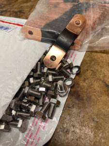
Cell interconnection would be done with copper bus bars. Also, some type of case and a way to protect the exposed cell terminals from accidental short circuit was needed.
In order for it to be a Solar Generator, a 120-volt AC inverter seemed like a good idea. Since it’s unlikely I’ll power anything but power tools and lighting, a “modified sine wave” inverter should be fine. I’ve had good luck with Bestek products so I selected their 1000-watt 12-volt to 120-volt model.
Last, but certainly not least was a method of charging the battery. The output of a solar panel with appropriate charge controller would be perfect since they can be configured to safely charge LiFePo4 batteries. I also wanted to charge the battery from 120-volt power. After looking all the choices over, I ended up purchasing a Victron Energy Blue Smart IP67 12-Volt 25 amp 120VAC Battery Charger. Not the cheapest choice, but able to charge at a relatively high current of 25 amps and equipped with bluetooth monitoring through a smartphone app.
Calculating Bus Bar size
I was able to find copper bus bars intended for this model of battery on eBay, but they can be made from any copper strap or bus material. Just keep in mind the maximum anticipated current and use the formula:
Ibb = w x t x MF
where Ibb is bus bar ampacity, w = width in mm, t = thickness in mm, and MF = material factor. Material factor is 1.2 for copper, .8 for aluminum, .6 for iron and 1.6 for silver.
As an example, the bus bars I found on eBay consisted of 4 pieces of copper strap, 22 mm wide by 0.5 mm thick. What is the current capacity (or ampacity)?
.5 mm x 22 mm x 1.2 MF = 13.2 amperes.
This copper strap can carry just over 13 amps safely. Copper straps can be added for more capacity, so 4 straps layered together can carry almost 53 amps. That’s enough for my Solar Generator’s anticipated use.
Warning: High Energy Storage
Now it’s time for the warning: Working with high-energy cells entails some risk and requires extreme care. Used improperly, large capacity LiFePo4 cells can be an intense fire hazard and are capable of producing several hundred amperes of current. Metal objects like a metal nut driver or wrench, if accidentally touched across the exposed cell terminals, can instantly be welded to the cell, resulting in a short circuit that can turn the metal cherry red with heat. That will destroy the cell, the tool, and ruin your day! You’ve been warned.
Safety First
To work as safely as possible, I like to wrap metal tools with electrical tape so a fumble-fingered moment won’t be any worse than bending over to pick up the tool. I also tape all the terminals except the ones I’m actually connecting with Kapton tape, then moving the tape as I go from terminal-to-terminal. It’s a little tedious, but greatly reduces the risk.
Building the Solar Generator
Selecting cells
I have hundreds of cells available, so selecting matching ones wasn’t hard. I was looking for 4 cells that measured as close to the same voltage as possible. New LiFePo4 cells are normally shipped with a partial charge of around 3.3 volts, and are stable at that voltage for a long time. In order to match cells, some battery builders recommend a process called “top balancing.”
This involves connecting several cells in parallel and bringing them to a full charge. The idea is to make sure the cells all discharge at the same rate in the finished battery. That way, you get maximum power from the battery. Since I was able to find four cells that measured within a few thousandths of a volt of each other, I decided to save the top balancing exercise for the next battery project.
I took the four cells and arranged them so that plus and minus terminals alternated across the top. I then tied them together with Kapton Polymide tape. This is a strong, high-temperature tape with silicon adhesive and is commonly used in battery construction.
Wiring the battery
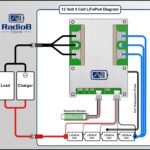
Once the cells were secured, I began wiring the battery. Bus bars, the main BMS connection and balancing leads, and a positive output lead must all be added. Full instructions and the diagram shown at left are included with the RadioB BMS. They are clear and easy to follow. The image at left leads to RadioB’s support documents and can explain the connections best.
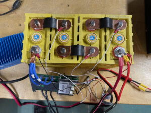
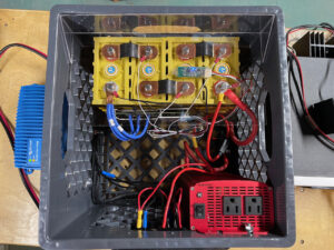
Connections to the lithium cell terminals are made with crimp-on connectors and high quality crimp tools are best. Three blue wires are connected in parallel between the BMS and the negative battery terminal, and that will require a relatively large crimp terminal. I find these hammer lug crimping tools work well for large copper lugs of 8 gauge or larger.
If you happen to be short a lug when building a battery like I was, one can be fashioned out of a piece of soft copper water line. Cut a piece about two inches long, hammer one half of it flat and drill a hole that will fit the M-6 bolt. The other half can be crimped around the blue BMS wires. It you look closely, you can see my homemade lug in the picture.
Wiring the Crate
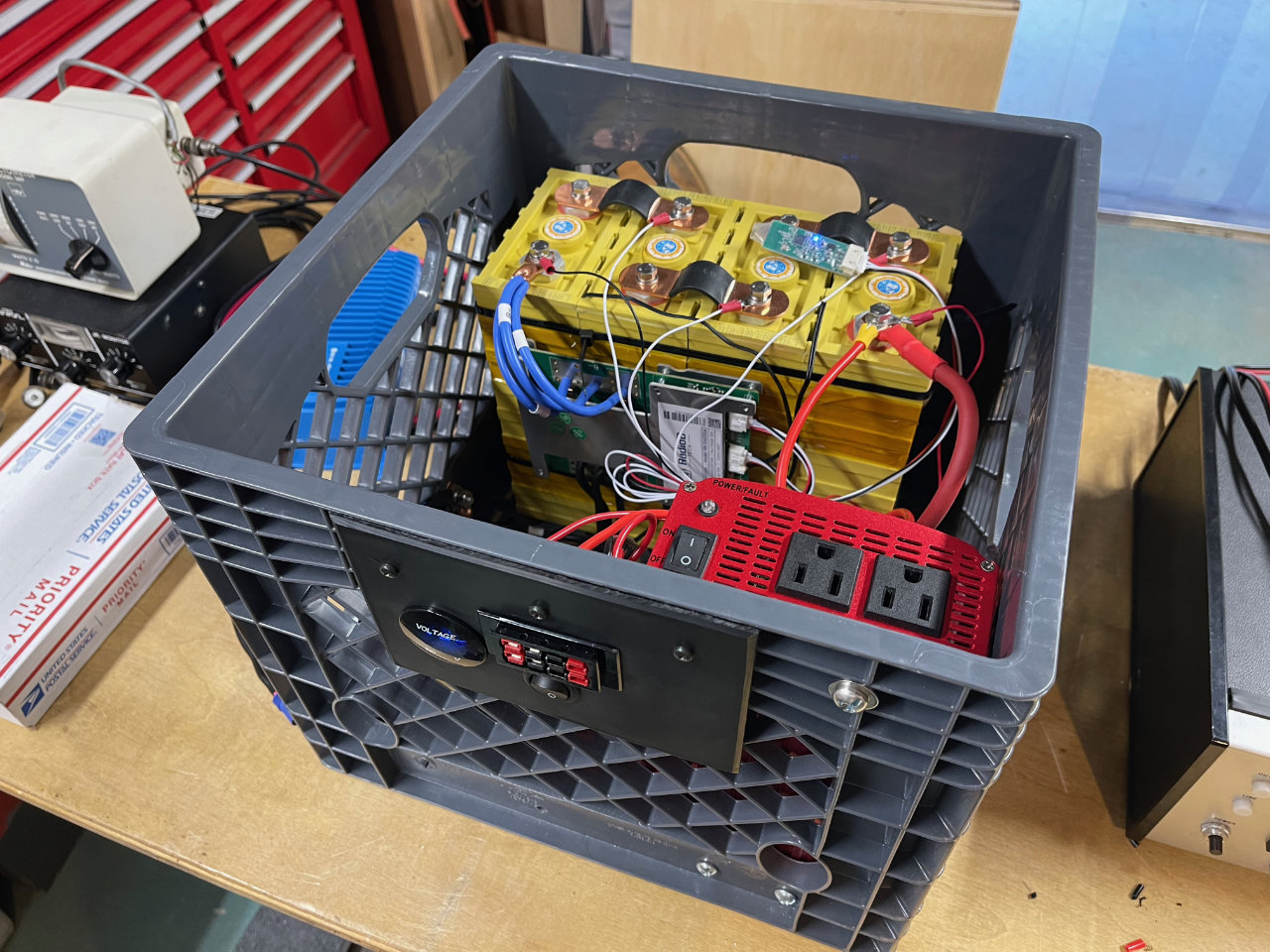
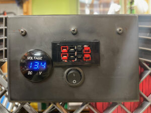
With the BMS wired, the circuit breaker, voltmeter and Anderson Power Pole connections were next. The black BMS wires are crimped to a lug that is attached to the stainless bolt and nut. It is visible on the left side of the milk crate. The positive lead of the battery is connected to the 80-amp circuit breaker/disconnect on the right side of the crate.
The Anderson Power Pole connectors, Digital voltmeter and Bestek inverter are all connected with appropriately-sized wires in parallel to the common negative and other side of the breaker/disconnect.
The five small wires that connect to several places on the battery are for cell balancing. They connect to (in order) battery negative, each cell junction and battery positive. It is critical they be connected in the correct order or damage will occur to the BMS.
When all eight cell connections are complete, tighten the M-6 bolts to between 12-15 Nm. The other device with small wires that connects to the BMS is the BlueTooth transceiver. It will be used to connect with the Smartphone app.
Protecting the cell terminals
Last of all, I thought it wise to put a protective shield between the battery tops, their bus bars and terminal connections and the rest of the world. Something metallic accidentally dropped there could do real damage. I used a sheet of clear Lexan polycarbonate sheet cut to fit on top of the battery. It is attached to the crate with another Lexan strip and corner braces. Plastruct plastic-weld fuses them together. The shield is attached to the crate with self-tapping screws. You can see it in place in the picture above.
Programming the BMS
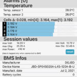
After checking all the connections again, I closed the switch on the breaker/disconnect. The digital voltmeter lit up and the inverter had power. The BMS comes with a default setting that will probably operate, but may not be optimum for the application. So I downloaded the XiaoXiangBMS App. It comes with a demo battery setting and default password. If everything is going well, you should see your new battery in the connection list. Mine appeared right away.
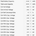
The XiaoXiang JDB BMS app allows you to tailor the BMS settings to your specific needs. I use an iPhone, but Android versions exist as well. I’m no expert on BMS programming, but I wanted to make sure the low and high cell limit voltages were set for the Winston LiFePo4 cells.
The data sheet has a page showing the discharge characteristics in graph form. They are shown for different discharge rates and battery temperatures. The graphics are hard to read with any precision, so I looked around the ‘net for typical LiFePo4 battery discharge curves. I found this Battery Voltage Chart. After doing a little work with a spreadsheet, I decided the Battery Voltage Chart was pretty close to the discharge curves shown in the Winston data sheet.
There is an online manual for the XiaoXiang JDB BMS app if you want to dig in, and it has a lot of capability. There are also videos on YouTube that discuss the RadioB BMS and the app, but what you find helpful will depend on your circumstances.
For the time being, I’m happy with the Solar Generator. I have used it several times to run corded power tools and it came in handy during the icing and power outage event last February. It has also provided valuable experience building and programming a lithium iron phosphate battery. The next battery, with twice as much capacity, will be for my amateur radio station. I’ll document it on the other blog: jimkerkhoff.comdocument it on the other blog: jimkerkhoff.com.



Pingback:Solar Power And Ten Tec's Awesome Closet Kilowatt | Jim Kerkhoff