Build A Great VPO – Part 3: Amp Repair
Build a great Virtual Pipe Organ (VPO)
A dying gasp . . .
Just before disassembling the Thomas Transistor organ to create a VPO, I tried turning it on for one last listen. I wanted to sample a few of the basic sounds for later use building a sample set or synthesizer patches. It hadn’t been used for quite some time, though I had no reason to suspect it wouldn’t work. Within a second or two of powering the organ, there was a loud pop, followed by a very loud hum. Time to get it on the bench!
A visual inspection . . .
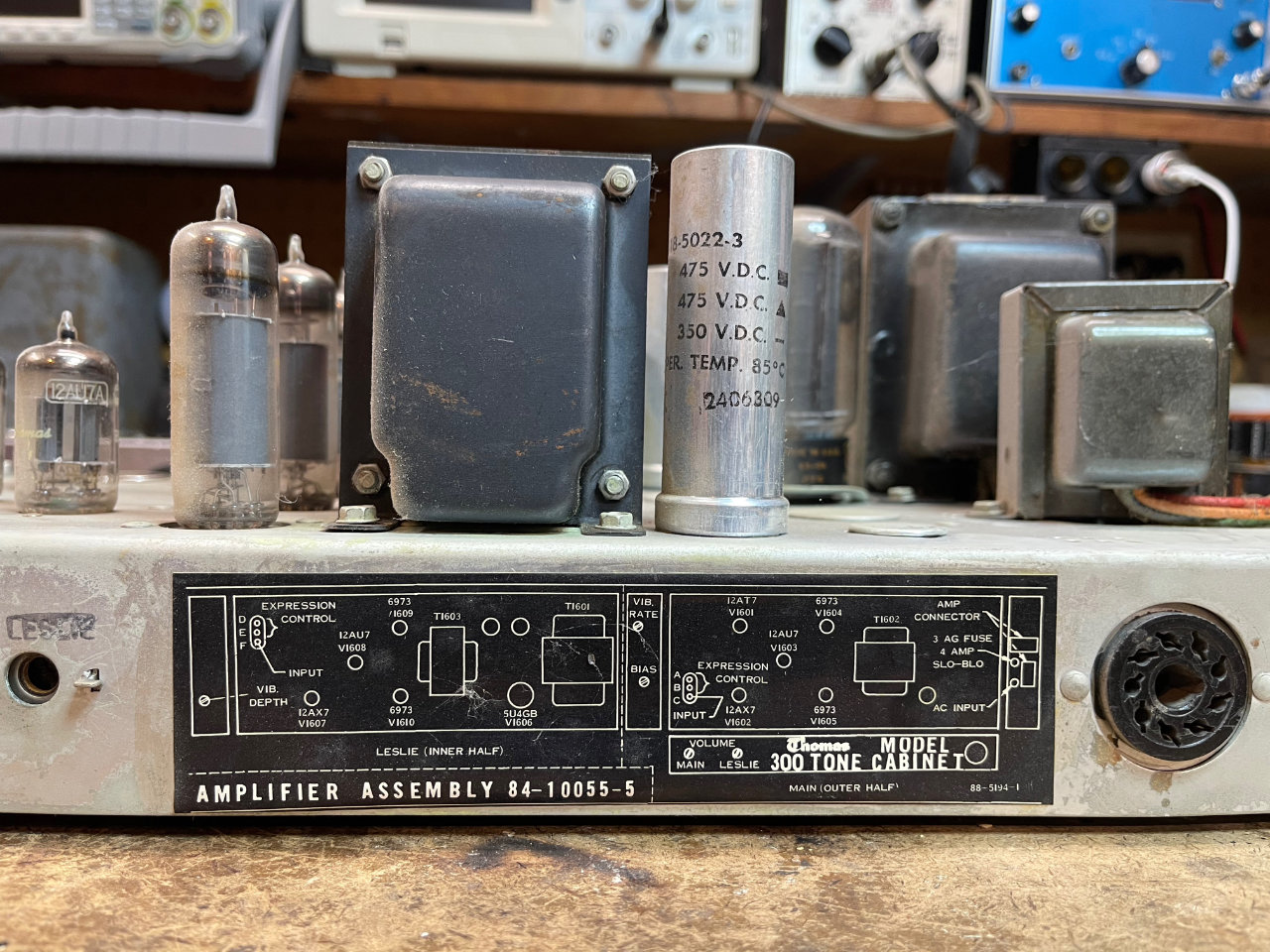
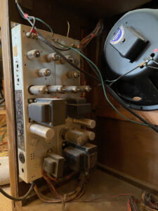
After removing it from the organ, I carried the amp out to the shop. I don’t know what I expected to find, but everything I’d heard over the years said to start with a visual inspection. Of course, that rarely reveals the problem. Oh, the occasional part that looks like it’s been hot, a capacitor that is bulging on one end or a tube that’s cracked — you can see those things. But most problems are less obvious.
. . . leads to a surprising discovery
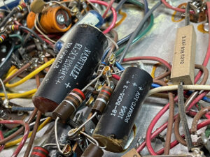
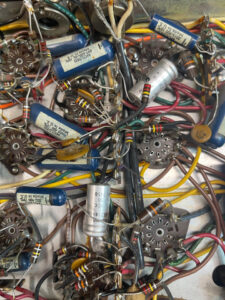
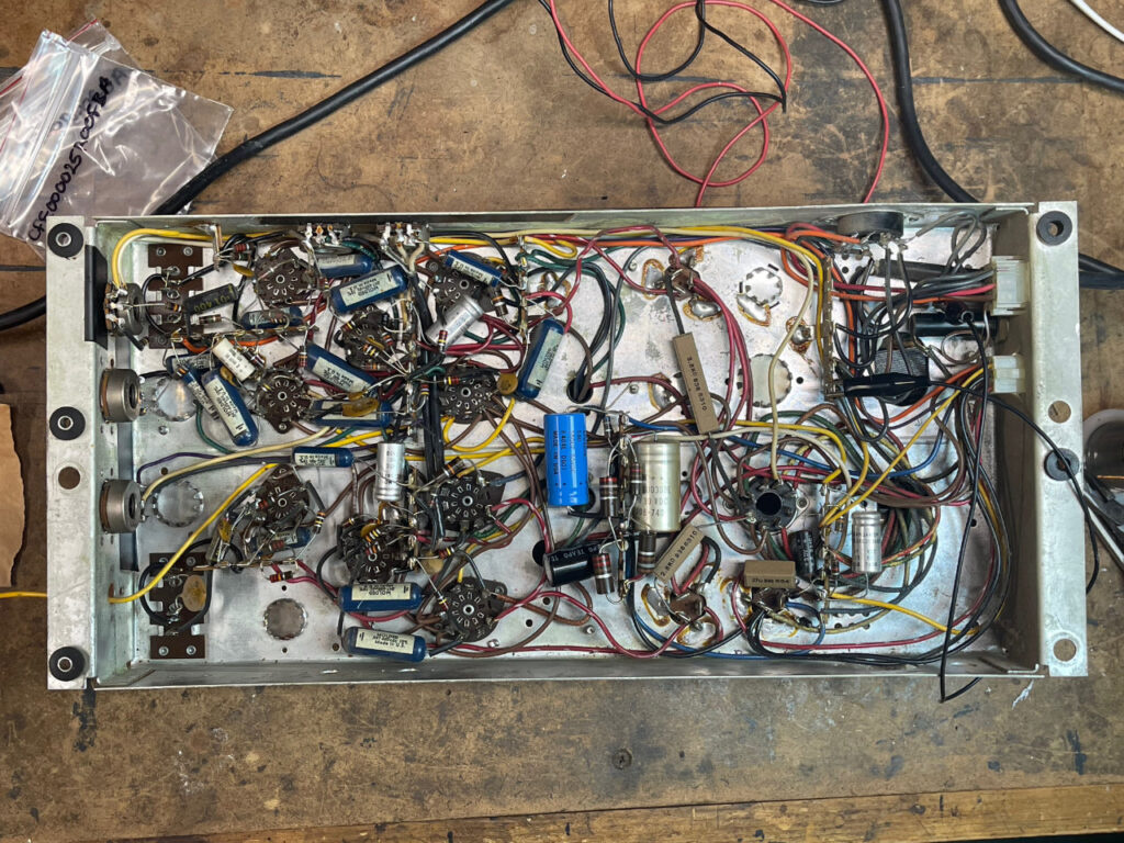
There was nothing unusual to report on the top side of the amp, but after turning it over to inspect the wiring, there is was. One lead of an electrolytic capacitor had broken off. Not at the end of the cap, but a break in the wire. Examining it closely, it looked like the lead had been nicked. Yet somehow it functioned for over fifty years. Then, after sitting for another 10 years, it just separated when the organ was powered. That’s one strange trip.
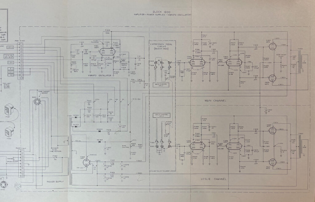
Skeptical of my good luck, I began comparing the wiring to the schematic. The broken capacitor lead was in the -15 to -20-volt power supply. It made sense. That could lead to unfiltered DC creating hum in the organ’s sound generator circuitry. A plausible explanation for the loud pop and hum.
The decision to replace electrolytic capacitors
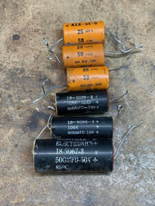
Since I was already servicing the amplifier, I decided to test and possibly replace the electrolytic capacitors. At about 60 years old, they were likely to be failing. A spot check or 3 or 4 caps revealed they were out of tolerance with respect to value, and showed a higher than acceptable equivalent series resistance (ESR). A failing capacitor may also have internal leakage. High ESR capacitors have greater losses and more internal heating problems. High ESR can reduce the life of aluminum electrolytic capacitors while reducing ripple current capacity in power supply circuits.
I’ve learned that electrolytic capacitors fail as they dry out and lose their capacitive function. The time needed to fail varies by how they were used and stored and how well made they were in the first place. In this respect, cheap parts are no bargain. Higher quality devices tend to be better sealed and therefore last longer.
Re-forming
As the capacitor fails, there are three observable effects: the value changes, internal leakage increases and the ESR rises. This failure can sometimes be reversed, especially in high quality capacitors, by applying a low voltage to the cap and increasing it slowly up to the capacitor’s working voltage. This treatment may reform the electrolytic film to make the cap usable again.
Capacitor testers
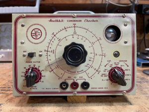
Back in the day, companies like Heathkit made capacitor testers that would measure value and check for leakage, and could, in a pinch, be used to reform a failing electrolytic capacitor. I don’t remember anyone talking about ESR when I was a young technician.
Today, inexpensive devices are available to check a capacitor’s value and ESR. We use that as an indicator of capacitor health. Those testers are available for $20 or $25. The long and the short of it? If a capacitor fails any of these tests, it should probably be replaced. I’ll make it even simpler. In equipment older than a few decades, it’s often faster and simpler to replace all of the electrolytic capacitors.
Non-polarized caps
Non-polarized caps, from a few picofarads to a µ farad or two, should also be checked for value and leakage. Out of tolerance or leaky caps should be replaced. A leaky interstage cap between the plate of one tube and the grid of another can lead to costly tube replacements. Positive-biasing a tube stage to draw too much current will burn it up.
I spot-checked the non-polarized caps, and all were within specs. They are the high-quality blue molded type, so I wasn’t expecting trouble. Anytime you see a waxed paper cap though, popular in much tube equipment until the 1960’s, just assume it’s bad and replace it.
One other tip: back in the day, caps were marked with a stripe around the end that was connected to the outer foil. That lead was always connected to the lowest potential — like chassis ground for bypass caps. You’ll want to match the practice with any replacement devices.
Testing
Powering safely
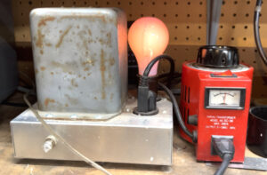
After replacing most of the electrolytic caps and testing a few resistors here and there, it was time for a listen. When powering an old or recently-serviced piece of tube equipment for the first time, I always use an isolation transformer, current limiter and Variac. Mine consists of an old military isolation transformer, 200 watt incandescent light bulb and 300-watt adjustable autotransformer.
This piece of test equipment should be on every bench because it allows one to work more safely on equipment that isn’t transformer isolated. Just remember: even with this protection, lethal voltages are still present in tube-based equipment. You’ve been warned!
The dim-bulb, current limited variable isolation transformer can also prevent damage by limiting current in the event of a short circuit in the device under test. Finally, it allows one to power a device slowly — especially helpful when the possibility of reforming capacitors exists. Don’t you just hate it when an eBay seller advertises “power on tested?” In older gear, that might mean you’re buying equipment that was damaged by just powering it on briefly.
The sweet sounds of success
So how does the amp sound? Great! I plugged my iPhone into it and listened to some recorded organ music. It sounded like the real thing. This will make for very satisfying performance audio. We’ll work on the pedals next. They need to be mated with the cabinet and converted to MIDI.
In no particular order, here are some of the other steps in the project:
- Repair audio amplifier (done)
- Adjust organ cabinet height to mate with pedal set
- modify AGO pedal set to add MIDI output
- remove tone generator, and related electronics
- remove and replace manuals with MIDI-equipped keyboards
- create and mount rack space for MIDI combiner and multichannel sound interface
Follow along as I fulfill my long-held dream of creating a Virtual Pipe Organ and bringing that magnificent sound into our home!

Pingback:Build A Great VPO — Part 2 : Salvage and Move | Roy Creek Ranch