How to Wire a Solar Power System – DC
Let’s Dig a Trench!
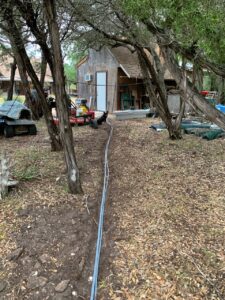
In the last post, we mounted the solar panel array. Now it was time for the solar power system low-voltage wiring. The array is about 50 feet from my shop, where the batteries and inverter are located. I planned to use two strands of #6 UF direct-bury cable to conduct the predicted maximum of 36 amperes to the shop. Being a believer in “eating the toad first,” I started the day by digging the shallow trench for the cables.
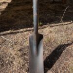
I used a special trenching shovel normal to make the trench about 4-inches wide. We have a thin layer of soil (2-4 inches) over a limestone caliche substrate, so I couldn’t go down very far. Fortunately, it wasn’t necessary since there will never be any heavy vehicles near the cable trench.
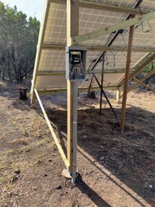
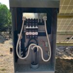
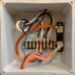
A DC load center was mounted on a support leg of the array, with a piece of conduit leading down into the trench. At the shop end, another piece of conduit led into the trench from fitting that went through the wall into a plastic electrical box inside. A total of about 120 feet of the #6 cable was needed for the two strands through the trench and vertical risers.
Managing Solar Power System with a DC Load Center
A DC load center with four DC breakers is a little expensive, but well worth the cost because it solves several problems. Most immediately, it serves as a gathering point for the panel wiring. The eight panels are wired in series by pairs, with each row forming a two-panel unit. Why wire in rows rather than columns? Because the panel pair will not produce power until both panels are illuminated and as the sun rises, it provides light to the top row first eventually lighting all four rows to the bottom. With the panels paired by rows, power generation starts earlier in the morning.
Each pair is then attached to a DC breaker inside the load center. This way, it is possible to isolate each pair of panels for troubleshooting or turn the entire array off. I learned how important disconnecting the array was when I forgot to do so while wiring the interior connections. At one point I had a blue-green arc going inside the shop. The open-circuit panel voltages are capable providing a substantial shock to the careless electrician, and with a 9-amp peak current, creating an arc! The load center is also weather-proof, protecting the breakers, busses and their connections.
A Little Solar Power Math
Originally, I wanted to run #4 UF (direct bury) cable to the shop, but it was harder to get and I realized that two #6 cables would do the same thing, while making a second panel bank possible in the future. The peak output of eight 270-watt panels is about 60 volts at 36 amps. With two strands of #6 cable (2-conductor) in parallel, the maximum voltage drop to the shop will be 0.85 volts, or a loss of about 30 watts — about 1.35%.
Adding a second array of 8 panels, the peak output rises to 72 amps. This will result in a loss of about 1.7 volts or about 2.7% — A little high, but the panels generate peak output for a brief time at midday, and only when the sun is exactly perpendicular to the array. That only occurs for a month or so each spring and fall with a fixed array. In other words, it is safe and the power loss in the transmission cables is acceptable. One final advantage with #6 cables: they are easier to work with than #4 cables. Much easier to push through conduit bends and wire inside of boxes.
Charge Controller Solar Power Wiring
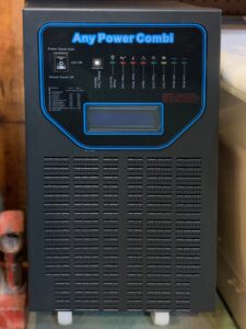
With the cables terminated inside the shop, it was time to complete the low-voltage wiring to the charge controller/inverter/charger. I bought the roller-mounted “tower” model, but other case styles are possible. If you are going to connect to a normal 240 VAC with neutral (120 VAC/120 VAC) system, be sure to request the “split phase” model when ordering. Like the Rainwater Project, a 40-amp MPPT charge controller, 6 KW inverter and mains charger are all combined in one device. This saves space and is very convenient.
The power from the solar array is connected through a 50-amp shunt to the MPPT charge controller input. The shunt, along with other connections to the plus and minus legs of the panel voltage allow for monitoring the instantaneous panel power generation. With this monitoring in place, it is possible to see how much power is being generated by the array at any time. There are digital monitors that tabulate and display all the charge data, but I installed retro analog meters instead. They meet my needs and look cool at the same time. More on the monitoring systems in the next post.
Battery Connections
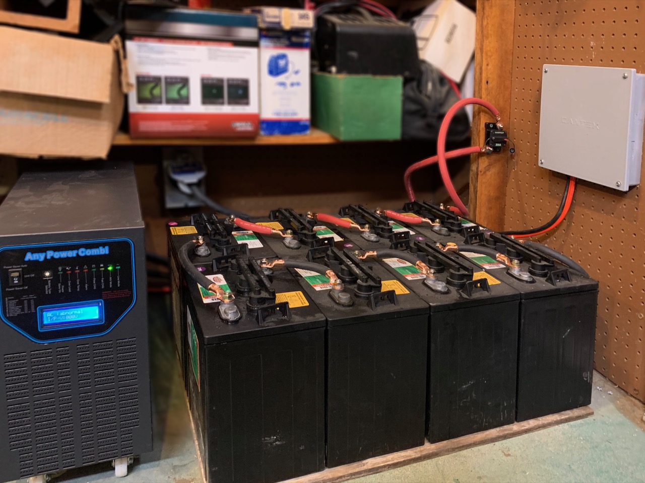
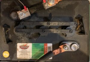
Now for batteries. Like the Rainwater Project, I used lead-acid Interstate brand golf cart batteries from Costco for the simple reason that they provide the best cost benefit ratio of any battery system. Eight 6-volt golf cart batteries provide a little over 10 kilowatt hours (KWH) of storage for around $900. Like the wiring for the panels to the charge controller, the batteries are connected to the inverter through a 100-amp shunt and digital monitor. A 200-amp DC breaker is included for safety and allow disconnecting the batteries from the inverter.
Connections between the batteries and the inverter are “OO” rubber insulated copper welding cable to handle the expected 125-amp average and 250-amp peak loads with ease. The 100-amp shunt allows for a digital monitor that displays battery voltage load amperage, load wattage and total KWH since last reset. That way, I can get some idea of power generated and delivered by the system.
Pingback:How to Wire a Solar System - Finished | Roy Creek Ranch